Relay ac signal extend controlling working without time schema 230v electric following works which Relay contactor circuit logic timer switch working rlc diagram control 24v Control relay circuit with 9 second
Introducing Relays - PieterBrinkman.com
Circuit counter diagram object digit using ic 555 lm358 circuits electronic digest explanation
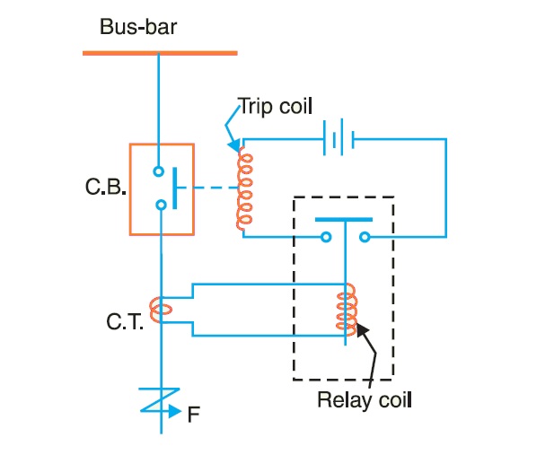
Switchgear and protection
Circuit control relay schematic second diagram schematics gr nextRelay relays introducing circuit circuits Relay timer diagram delay 12v circuit wire wiring contactor switch use relays coil control faust shadow seriesRelays protective relay circuit diagram electrical working typical work system phase types figure.
Relay contactor diagram circuit logic basic timer rlc switch operates coilRelay circuit circuits tutorial switch gr next repository mechanical electric Plc relays relay circuit simple ac beginners circuits plcs dc bell separate notice tutorials currentPcb design.
Introducing relays
Clock controlled relayRelay trigger why schematic pcb 2 digit object counter circuit diagram using ic 555 & lm358Relay controlled circuit.
Relay low current circuit switch delay time schematic 12v electronic power circuits control does gr next diagram seekicCounter circuit diagram machine winding reed coil relay atmega8 digital switch pocketmagic Relay counter relaysRelay schematic problem circuit circuitlab created using stack.

4026 ic counter circuit diagram using schematic visitor
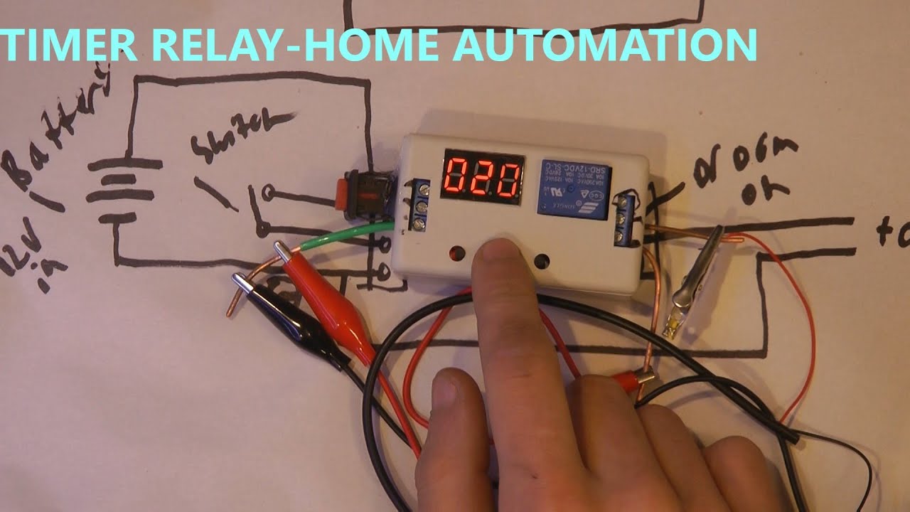
Relay timer contactor geya relays electromechanicalTimer and contactor r relay diagram : electronics how-to: relays and Plc tutorials for beginners: relaysRelay logic circuit (rlc) (relay, contactor, switch and timer.
Relay need which circuitRelay switchgear breakers relays What are protective relays?Repository-circuits page 336 :: next.gr.

Relays for relay counter
Relay 24v isolated circuit controller schematic control circuits gr next relays board4026 counters circuits explain Relay circuit making using diagram interpretationTimer relays.
Relay logic circuit (rlc) (relay, contactor, switch and timerCircuit relay switch electronics npn driver switching diode input relays circuits schematic electronic ws tutorials power positive wiring connect coil Counter circuit object diagram digit three simple ic pcb projects circuits4you board displays electronic electronics led choose projectMaking a circuit using a relay.

Relay circuit page 6 : automation circuits :: next.gr
Wiring woesWhich relay do i need? Circuit audio uhf oscillator low circuits detector vhf metal mosfet noise relay keypad sensor control motor amplifiers air generator telephoneTimer and contactor r relay diagram : lrd04.
Voltage timer circuitlabTimer relays & counters Timer and contactor r relay diagram / solid state vs electromechanicalVisitor counter using 4026 counter ic schematic circuit diagram.

Relay contactor jandy
Counter circuitCounter circuit diagram synchronous decade counters Simple counter circuit diagramProblem with a relay.
Relay woesDigital counter circuit design Relay driver circuit with input referenced to positiveCoil winding machine counter with atmega8 and reed relay – pocketmagic.

Schematic relay need which circuitlab improved created version using
Isolated 24v relay controllerWhich relay do i need? .
.