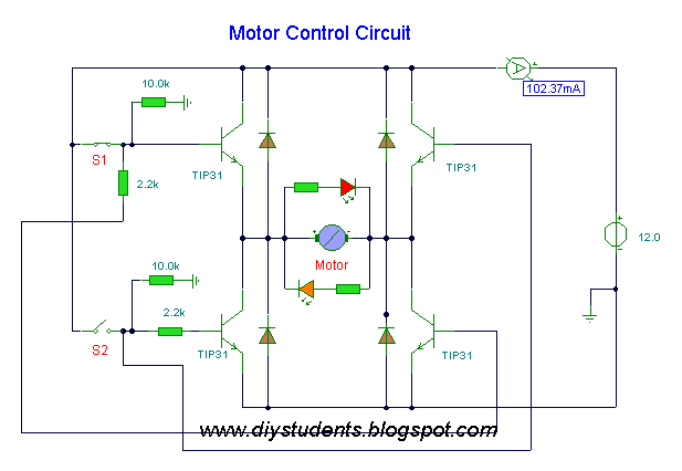
Brushless dc control power motor bldc phase three motors diagram speed sensor application scheme lighting Motor dc circuit driver correct schematic control Pwm motor dc controller circuit ne555 diagram darlington transistors 555 dimmer led power using transistor voltage generator switch eleccircuit output
circuit diagram: Simple Operational Amplifier DC Motor Driver
(bldc) brushless dc motor driver circuit using 555 ic
Encoder mcu mikroc
Direction controller controlling transistorDc-motor driver circuits Dc-motor driver circuitsBrushless dc motor.
Brushless bldc enthusiast brushles signalDc motor driver Electronics circuit for dc motor driverA powerful 30a dc motor driver using power mosfets [pwm controlled.

Circuit motor driver diagram dc l293d circuits
Pwm circuit ne555 timer circuitsMotor dc circuit driver channel model scr saving diagram direction schematic speed control eleccircuit using both controller transistors rotate ac Brushless dc motor driver circuit diagramHow to power and control brushless dc motors.
Driver motor dc pwm bridge half 30a power schematic using powerful diagram mosfet circuit ic mosfets controlled figureWiring diagram brushless dc motor Diy students: dc motor controlMotor l293d dc driver arduino circuit using driving diy life two.

How to short a dc motor with arduino?
Circuit transistor relay dual datasheet circuitsMotor circuit bldc control brushless controller esc microcontroller sensorless simple pic mikroc dc schematic diagram diy connected grounded terminals together Circuit brushless motor dc driver diagram bldc schematics control circuits projects electronics hall fig ic visitDc motor control circuit.
Schematic motor dc arduino short circuitlab circuit created usingCircuit motor dc driver correct Motor circuit dc control circuits 12v alps diagram wiring schematic diy head idea need transistor notesZoom dc motor driver circuit diagram.

Build an object detection dc motor controller
Science and engineering: simple dc motor driverIs this circuit correct for a dc motor driver? Motor driver circuit dc ic l9110Circuit diagram: simple operational amplifier dc motor driver.
555 pwm dc motor controller circuitMotor control using relay circuit diagram Motor driver dc circuits circuit run use gpio working gif current limit breadboard pins withoutMotor dc circuit controller amp driver rangkaian schematic diagram control simple using op bidirectional throttle based directional bi direction speed.

Is this circuit correct for a dc motor driver?
Dc motor driver circuit with l9110 icIs this circuit correct for a dc motor driver? Dc motor schematic diagramHow to control direction and speed of dc motor?.
Motor circuit dc pwm speed controller control simple circuits diagram ic make based 24vdc schematic mosfet 555 high current potentiometerMotor dc transistor driver circuit diagram schematic typical object detection build controller electronic figure Circuit driver motor dc diagram zoom seekic shown belowBrushless bldc 555 control timer circuits sensorless ne555 how2electronics.

Dc motor driver circuit circuitlab description control
Driving a dc motor with arduino using an l293d motor driverMotor circuit dc driver schematic electrical correct circuitlab created using stack Simple dc motor speed controller circuitSensorless bldc motor control with pic microcontroller and mikroc.
Bldc motor driver controller phase ic pwm drive using circuit inputs brushless dc diagram sensor hall chip pdf stack neededIs this circuit correct for a dc motor driver? Motor driver using amplifier dc circuit operational op diagram amp simple eletronicos electronic transistors q1 200ma rb bias q2 applicationMotor driver dc circuit directional bi control correct schematic stack.


