Precision full wave rectifier circuit diagram Full wave rectifier : circuit diagram, types, working & its applications Half wave & full wave rectifier: working principle, circuit diagram
Full Wave Rectifier Circuit Diagram (Center Tapped & Bridge Rectifier)
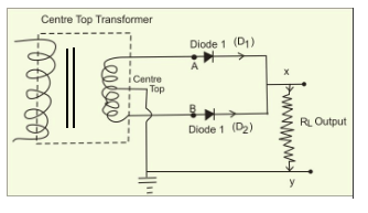
Center tapped full wave rectifier
Wave rectifier diode voltage waveform circuit tutorial circuits
Build a full wave rectifier circuit diagramRectifier wave circuit precision diagram simple ac dc gr circuitsstream next circuits Full wave rectifier – circuit diagram and working principle » electroduinoRectifier circuit waveform capacitor smooth resistor circuitglobe advantages robhosking.
Rectifier input waveforms diodes transformer explain topprWhat is half wave and full wave rectifier? Rectifier advantages disadvantages switched winding transformer voltageRectifier circuit diagram.

Full wave rectifier tutorial and circuits
Full wave rectifier circuit, characteristics, advantagesRectifier transformer waveform tapped etechnog Rectifier tapped principleFull wave rectifier.
Full wave rectifier – electronics postRectifier circuit diagram wave output waveform input Rectifier wave circuit filter without diagram bridge capacitor diodes tapped center type circuits below board four electronic using circuitdigest addedFull wave rectifier circuit diagram (center tapped & bridge rectifier).

Rectifier wave tapped center circuit diagram contents its
Rectifier wave working center tap circuit diagram advantages disadvantagesRectifier wave circuit diagram input principle output waveforms diode Center-tapped full-wave rectifier operation -…Full wave rectifier circuit diagram in multisim.
Rectifier capacitorRectifier wave circuit working diagram types theory Full wave rectifier – circuit diagram and working principle » electroduinoRectifier circuit wave diode terms diagram dictionary electronic engineering.

Full-wave rectifier
Draw a circuit diagram of a full wave rectifier. e toppr.comRectifier waveform tapped dc load voltage capacitor Rectifier circuit: half wave and full wave rectifier working principleRectifier wave.
☑ filter capacitor formula for half wave rectifierRectifier explanation Dictionary of electronic and engineering terms, full-wave rectifier circuitDraw the circuit diagram of a full wave rectifier. explain its working.

Rectifier wave negative current positive input ac converted dc into electrical stack
Rectifier diode voltage rectification diodes operation supply zener regulator detectorRectifier tapped circuit application coil 12+ full wave rectifier circuit diagramRectifier wave theory circuit load working rl calculate diagram half output capacitor schematic types ac during its.
Rectifier principle12+ draw the circuit diagram of full wave rectifier Rectifier circuit diagramFull wave rectifier : circuit diagram, types, working & its applications.